In this application note is a short description of utilizing 'Agilent 34970A Data Acquisition/Switch Unit' with '34903A 20-Channel Actuator / General-Purpose Switch' with Omega software to achieve automated rotating of four electrodes for Van der Pauw measurements.
Details of the actuator module
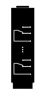 |
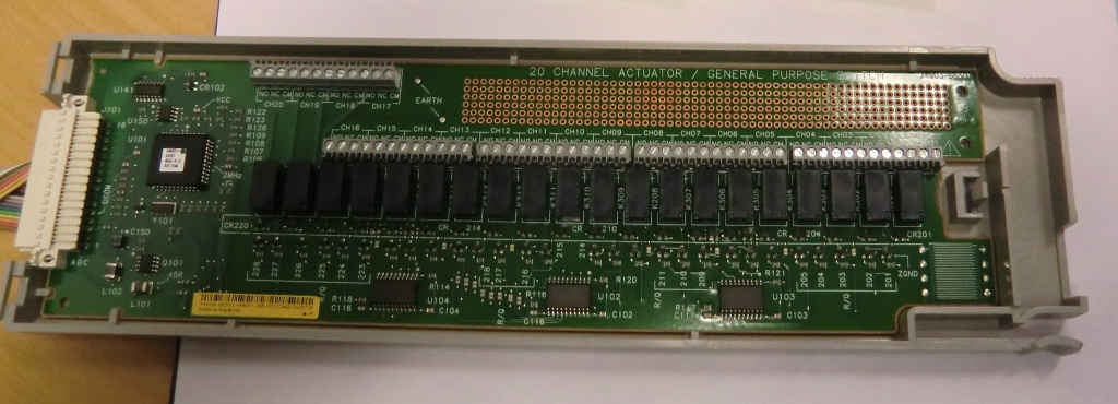
34903A 20-Channel Actuator / General-Purpose Switch Use this module for those applications that require high-integrity contacts or quality connections of non-multiplexed signals. This module can switch 300 V, 1 A (50 W maximum switch power) to your device under test or to actuate external devices. Screw terminals on the module provide access to the Normally-Open, Normally-Closed, and Common contacts for each of the 20 switches. A breadboard area is provided near the screw terminals to implement custom circuitry, such as simple filters, snubbers, or voltage dividers. |
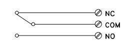 |
This module contains 20 independent, SPDT (Form C) latching relays. Screw terminals on the module provide access to the Normally-Open, Normally-Closed, and Common contacts for each switch. This module does not connect to the internal DMM. A breadboard area is provided near the screw terminals to implement custom circuitry, such as simple filters, snubbers, and voltage dividers. The breadboard area provides the space necessary to insert your own components but there are no circuit board traces here. You must add your own circuitry and signal routing. |
 |
|
Intended behaviour
 |
The state of the switches 1-4 (later referred as channels) are all changed at the same time to either open or closed, effectively achieving rotating electrodes; The instrument contacts HC, HV, LV and LC (High current, High voltage, Low voltage and Low current) connecting to the electrodes A, B, C and D. |
Wiring details
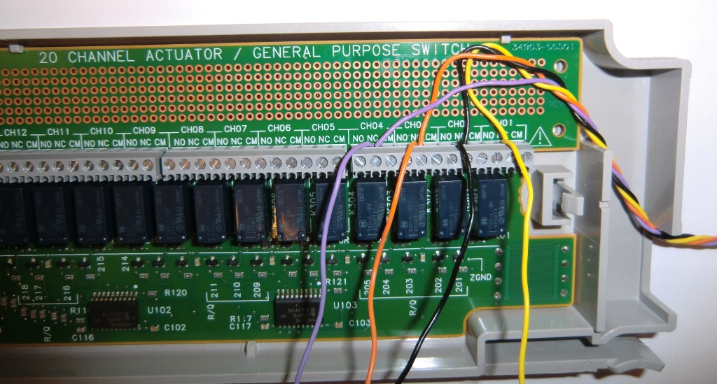 |
First the four electrode wires are connected to each channel on the NC (Normally closed) terminal, with additional short wire piece also attached to the terminal. |
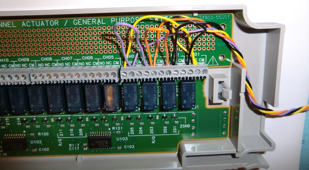 |
The additional piece from each terminal is connected to the NO (Normally open) terminal of the previous channel. Channel 1 NO connects to channel 4 NO. |
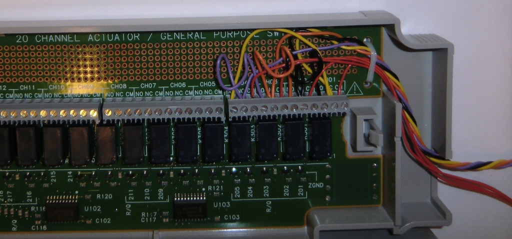 |
The four instrument terminal wires are connected to each channels CM (Common) terminal. |
Rotating the electrodes with Omega software
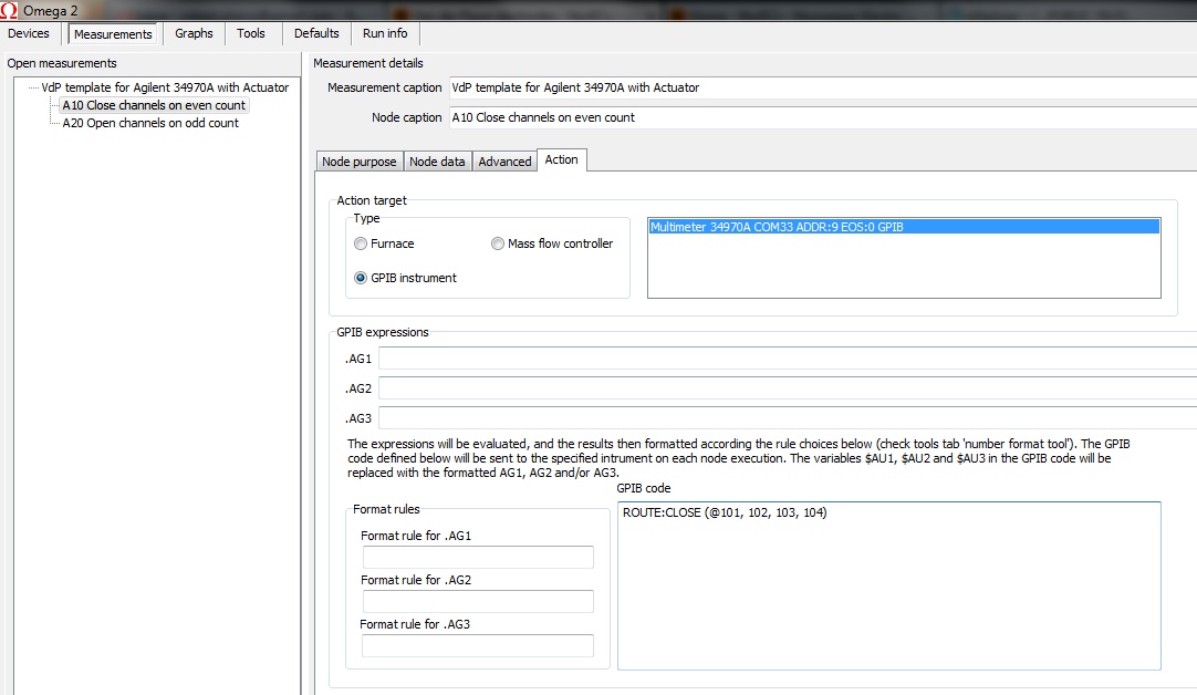 |
The channels were opened on every second measurement loop and closed the other every second loop. Measurement file for the control can be found in the files section, named 'VdP template for Agilent 34970A with Actuator.mea' |
