|
|
How can I seal a disk sample to a sample support tube with a gold gasket?
In general, the degree of sealing is always variable and always depends of the alignment of the ring, sample surface etc. Therefore, follow our recommendations below before starting the sealing process:
- Make sure that there is a uniform press/force from all three spring loads: equal length of alumina parts and spring stiffness. If the electrode area pointing upwards does not cover the whole surface (a reduced area compared to total cell area) the spring load force cannot be too strong. This may lead to a high mechanical stress in the sample that may lead to cracks upon heating.
- The support tube rim which is in contact with gold ring (and indirectly cell) must be level and smooth.
- Use an uniform gold ring.
- Check that the top alumina part from the spring load assembly is nice, uniform and smooth.
Gold does not act as a glass - it has a more defined melting point. If you are much below it nothing happens, if you are a little too high, it runs away. In our experience you need to
1) go to a temperature as close as possible to the gold melting point (1064°C). In practice we go to 1000°C, then more slowly to 1050°C (but only to avoid the risk of shooting over the melting point), then slowly (e.g. 0.5 C/min) to 1055 - 1060°C; use the ramp rate feature of the furnace,
2) wait longer than you might expect - depending on how close to the melting point you are,
3) use a monitoring that tells you continuously how good the seal is (so that you can interrupt and cool a little at the right point),
4) avoid any gas pressure buildup once the seal forms that would press the gold in or out,
5) avoid having a radially unsymmetrical temperature gradient (keep the cell in the middle of the furnace so that the seal softens equally all around).
- Combining 3 and 4 requires some thinking: You could in principle pump on the inner chamber and monitor the pressure. Once it seals it chokes and you have it. But the pressure drop could blow the seal open a few seconds later. Instead, feeding e.g. one gas to one chamber and another to the other chamber, whilst monitoring e.g. the outlet from the inner chamber (via the thin tube) with a MS or GC allows you to follow the sealing process without enforcing a total pressure gradient. We use the latter method with a MS or GC and try to use gases that will be used in the actual measurements to reduce the risk that the sample cracks upon changing pO2. For hydrogen permeable materials we thus use wetted H2+N2 (formier gas) on the outside and wet or dry Ar on the inside. This lets us use e.g. the N2 signal in the inner chamber outlet for checking the seal. It of course may take a little experience to know when you have a tight seal so that you can cool it. The same gases are usually then used onwards in the actual measurements: N2 gives the leakage and H2 gives the permeation. (Using He+H2 would be better.) This is then kept until tight. It may take one or several hours depending on the accuracy of the thermocouple. After seal is OK, cool to 1000°C or 1050°C and start taking measurements at decreasing temperatures. Unfortunately, the gold seal is not all that soft and forgiving when strained. But with proper monitoring of the leakage gas signal, you will have control.
- The leakage can be checked by applying a small overpressure in the outer compartment, for instance by bubbling its outlets through a few centimeters of water. While the cell is very leaky, the gas in this compartment will leak through and out of the other compartment. As the seal improves, you can monitor this on the height of the water columns and eventually the bubbling from the outer compartment. If you have fine control of pressure difference between the two chambers, you can in our opinion also test fuel cells with the remaining moderate leakage. Especially if one of the gases (fuel or the oxidant) is diluted. Check our Probble product page.
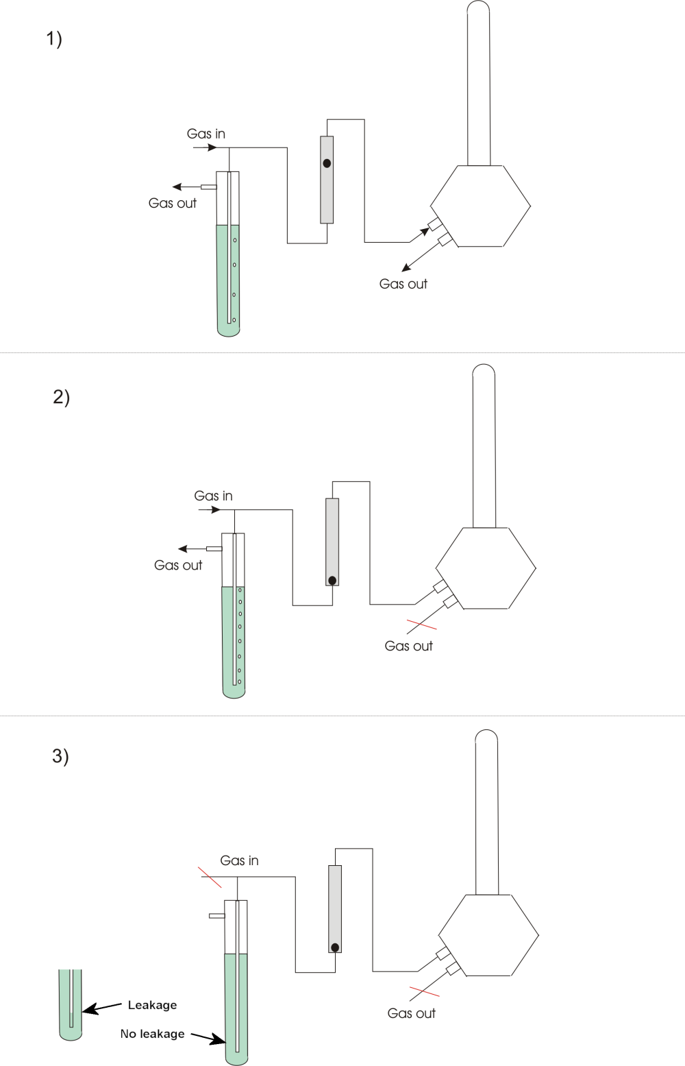
- Another procedure for checking both the total cell gas tightness and the tightness between the cell chambers is also based on using slight overpressure (see figure below). Connect a gas flow to an inlet of the cell with a T-connection to an overpressure controller, e.g. a column of water (or oil), followed by a flowmeter (e.g. a rotameter with fine scale). Allow gas to flow to the cell (1). Close the cell outlet(s) if not done already. The flow in the flowmeter should now go to zero, as a first check (2). If it remains at a stable non-zero flow, there is a large leakage. This may often be spotted by using soap water (or the commercial “Snoop”) at suspected leaks. If the flowmeter does go to zero, there may still be small leaks below the detection limit of the flowmeter. Check this by stopping the gas flow to the system (before the overpressure stage). The bubbling in the overpressure stage stops. If the apparatus is gas-tight the column remains at the full height (3). If not, the overpressure and the column height decrease. The column should be stable for an hour or more.

|
|
 Delivery and Shipping
  Electrode contact assemblies, springs, gas tubes, etc.
  Furnaces
  ProboStat - General
  ProboStat - Maintenance
  ProGasMix
  Samples
  Sealing
  Support
  The company
  Thermocouples and temperature control
  Troubleshooting - ProboStat
  Visiting Oslo


