Click on the categories to display the questions. Click on the questions to display answer. (Click to display all close all)
|
How to connect to measurement instrument?
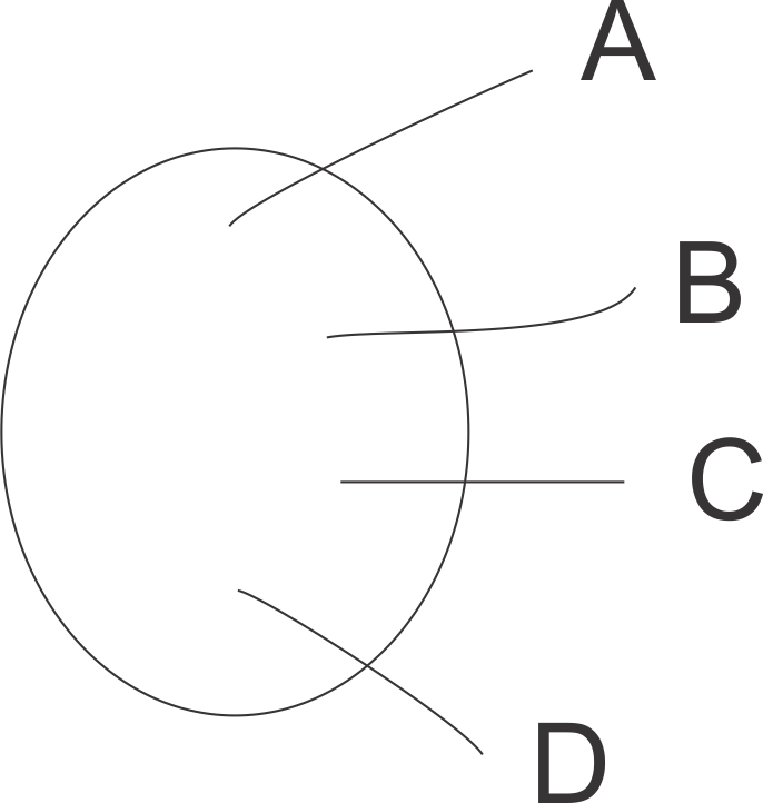
Many instruments have different naming for their various terminals and ProboStat has its own naming, so it may be confusing at first to know how to connect the instruments. There is no fixed rule what to connect to where, instead the user needs to read the instrument manual to know how the instrument operates. On the picture the circle is the sample and the lines represent electrode contacts. In general AC and DC resistance and AC impedance measurements are done by applying current through sample from A to D. In order to get results, voltage needs to be measured. It can be measured inside the instrument or at the sample on B and C wires, this is done automatically by the instrument depending on the mode it is operated on, but making the right connections is left to the user. Examples on the naming of electrode contacts and instrument terminals for 4-point measurements.
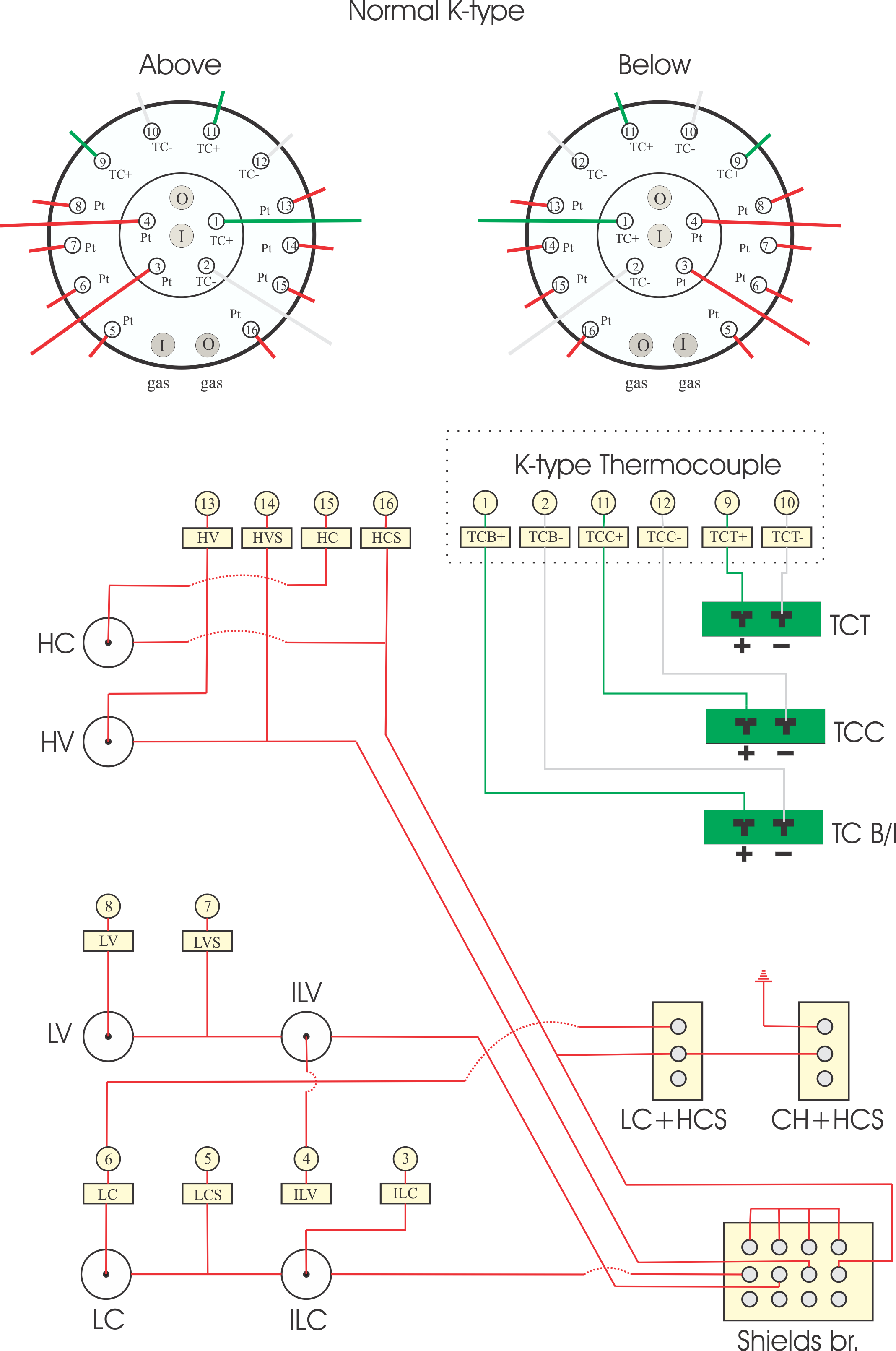
There are as many permutations of these as there are combinations of the trinity "measurement method / sample holder / instrument (and module/card)". Therefore it is necessary for the user to know the measurement method they are using, the sample holder schematics and the instrument. They should therefore read all the manuals, and draw a schematic of the circuit they have, all the way from the instrument to the sample. Each ProboStat is supplied with extensive manual as well as wiring schematics similar to the one below.
Additionally, for AC type instruments each of these wires is shielded (surrounded with another lead to minimize the measurement wire picking up interference). The instruments have their own preferred methods to operate these shields, and depending on the instrument the shields may have to be connected in one way or the other. Some instruments require all shields to be connected together, and/or also to the ground and some instrument can even be broken if the shields are connected/operated wrong. The switches on ProboStat offer the user an easy way to connect or separate the shields from each other and the chassis of the ProboStat. It is important also to understand that the ProboStat chassis itself may or may not be connected to the ground depending how it is fixed, and this may cause ground loops. In addition many instruments have different terminals; screw terminals, bnc contacts, thermocouple mini sockets, banana -sockets or cables with -plug, triax, or high voltage plugs. For this purpose ProboStat systems come with electrical accessories bag containing arrangement of adapters suitable for most common situations. NORECS also offers training at our facilities in Oslo or on-customer-site also. |


